Internet Protocol Address : An Internet Protocol (IP) address is a number which assigned to each device connected to a computer network that
uses the Internet Protocol for communication.
The number of networks and the number of hosts per class can be derived by this formula:
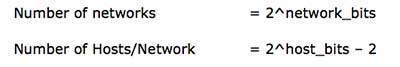
When calculating hosts' IP addresses, 2 IP addresses are decreased because they cannot be assigned to hosts, i.e. the first IP of a network is network number and the last IP is reserved for Broadcast IP.
Internet Protocol Version 6 : In IPv6, the address size was increased from 32 bits in IPv4 to 128 bits or 16 octets, thus providing up to 2128 (approximately 3.403×1038) addresses. This is deemed sufficient for the foreseeable future.
An IPv6 address is made of 128 bits divided into eight 16-bits blocks. Each block is then converted into 4-digit Hexadecimal numbers separated by colon symbols.
For example, given below is a 128 bit IPv6 address represented in binary format and divided into eight 16-bits blocks:
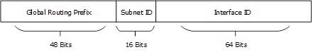
[Image: Global Unicast Address]
Global Routing Prefix: The most significant 48-bits are designated as
Global Routing Prefix which is assigned to specific autonomous system.
The three most significant bits of Global Routing Prefix is always set
to 001.

[Image: Link-Local Addres Link-local addresses are used for communication among IPv6 hosts on a
link (broadcast segment) only. These addresses are not routable, so a
Router never forwards these addresses outside the link.
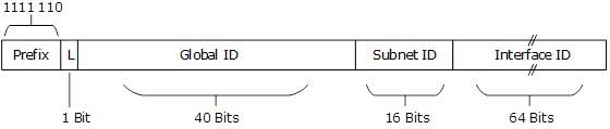
[Image: Unique-Local Address]
Prefix is always set to 1111 110.
L bit, is set to 1 if the address is locally assigned. So far, the meaning of L bit to 0 is not defined.
Therefore, Unique Local IPv6 address always starts with ‘FD’.
[Image: IPv6 Unicast Address Scope]
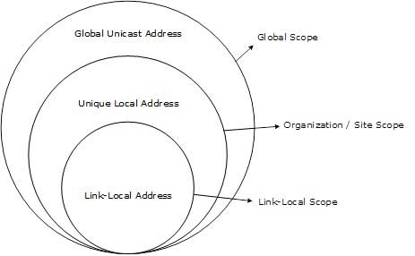
The scope of Link-local address is limited to the segment. Unique
Local Address are locally global, but are not routed over the Internet,
limiting their scope to an organization’s boundary. Global Unicast
addresses are globally unique and recognizable. They shall make the
essence of Internet v2 addressing.
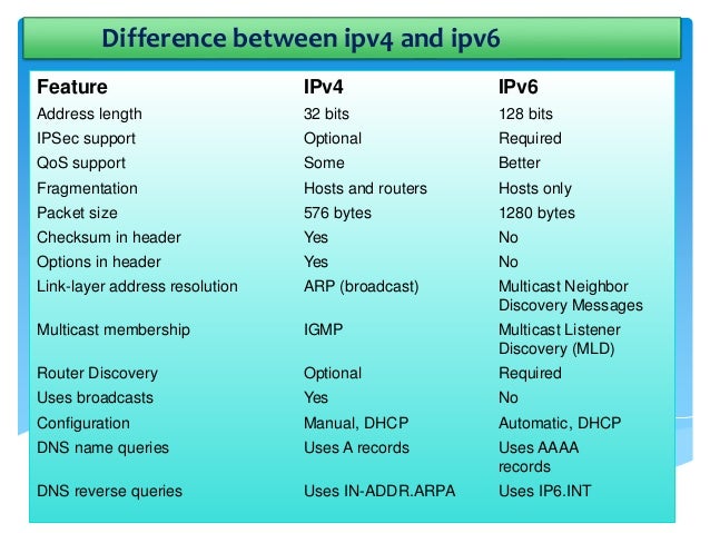
Two types of IP version mainly use one is IP version 4 or (IPv4) and IP version 6 or (IPv6).
Internet Protocol Version 4 : Internet Protocol version 4 (IPv4) is the fourth version in the
development of the Internet Protocol (IP) and the first version of the
protocol to be widely deployed. IPv4 is described in IETF publication
RFC 791 (September 1981), replacing an earlier definition (RFC 760,
January 1980).
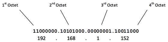
An IP address in IPv4 is 32-bits in size, which limits the address space to 4294967296 (232) IP addresses.IPv4 addresses are usually represented in dot-decimal notation,
consisting of four decimal numbers, each ranging from 0 to 255,
separated by dots, e.g., 172.16.254.1. Each part represents a group of 8
bits (octet) of the address.
The first octet referred here is the left most of all. The octets
numbered as follows depicting dotted decimal notation of IP Address:The number of networks and the number of hosts per class can be derived by this formula:
When calculating hosts' IP addresses, 2 IP addresses are decreased because they cannot be assigned to hosts, i.e. the first IP of a network is network number and the last IP is reserved for Broadcast IP.
Class A Address
The first bit of the first octet is always set to 0 (zero). Thus the first octet ranges from 1 – 127, i.e.Class A addresses only include IP starting from 1.x.x.x to 126.x.x.x only. The IP range 127.x.x.x is reserved for loopback IP addresses.The default subnet mask for Class A IP address is 255.0.0.0 which implies that Class A addressing can have 126 networks (27-2) and 16777214 hosts (224-2).Class A IP address format is N.H.H.H.Class B Address
An IP address which belongs to Class B IP Addresses range from 128.0.x.x to 191.255.x.x. The default subnet mask for Class B is 255.255.x.x. Class B has 16384 (214) Network addresses and 65534 (216-2) Host addresses. Class B IP address format is N.N.H.H.
Class C Address
The first octet of Class C IP addresses range from 192.0.0.x to 223.255.255.x. The default subnet mask for Class C is 255.255.255.x. Class C gives 2097152 (221) Network addresses and 254 (28-2) Host addresses.Class C IP address format is: N.N.N.H.
Class D Address
Very first four bits of the first octet in Class D has IP address rage from 224.0.0.0 to 239.255.255.255. Class
D is reserved for Multicasting. In multicasting data is not destined
for a particular host, that is why there is no need to extract host
address from the IP address, and Class D does not have any subnet mask.
Class E Address
This IP Class is reserved for experimental purposes only for R&D
or Study. IP addresses in this class ranges from 240.0.0.0 to
255.255.255.254. Like Class D, this class too is not equipped with any
subnet mask.
Address Structure
An IPv6 address is made of 128 bits divided into eight 16-bits blocks. Each block is then converted into 4-digit Hexadecimal numbers separated by colon symbols.
For example, given below is a 128 bit IPv6 address represented in binary format and divided into eight 16-bits blocks:
0010000000000001 0000000000000000 0011001000111000 1101111111100001 0000000001100011 0000000000000000 0000000000000000 1111111011111011
Each block is then converted into Hexadecimal and separated by ‘:’ symbol:
2001:0000:3238:DFE1:0063:0000:0000:FEFBEven after converting into Hexadecimal format, IPv6 address remains long.
Global Unicast Address
This address type is equivalent to IPv4’s public address. Global Unicast addresses in IPv6 are globally identifiable and uniquely addressable.
Link-Local Address
Auto-configured IPv6 address is known as Link-Local address. This address always starts with FE80. The first 16 bits of link-local address is always set to 1111 1110 1000 0000 (FE80). The next 48-bits are set to 0, thus:Unique-Local Address
This type of IPv6 address is globally unique, but it should be used in local communication. The second half of this address contain Interface ID and the first half is divided among Prefix, Local Bit, Global ID and Subnet ID.
Scope of IPv6 Unicast Addresses:
Network