Sunday, 21 January 2018

Routing Basics

Routing is used for taking a packet from one device and sending it through the network to another device on a different network. Routers don’t really care about hosts they only care about networks and the best path to each network. The logical network address of the destination host is used to get packets to a network through a routed network, and then the hardware address of the host is used to deliver the packet from a router to the correct destination host.


If your network has no routers, then it should be apparent that you are not routing. Routers route traffic to all the networks in your internetwork.

To be able to route packets, a router must know, at a minimum, the following:
  1. Destination address
  2. Neighbor routers from which it can learn about remote networks
  3. Possible routes to all remote networks
  4. The best route to each remote network
  5. How to maintain and verify routing information
  6. The router learns about remote networks from neighbor routers or from an administrator.

The router then builds a routing table (a map of the internetwork) that describes how to find the remote networks.

Static Routing

It is used, the administrator is responsible for updating all changes by hand into all routers. Typically, in a large network, a combination of both dynamic and static routing is used.

Dynamic Routing

A protocol on one router communicates with the same protocol running on neighbor routers. The routers then update each other about all the networks they know about and place this information into the routing table. If a change occurs in the network, the dynamic routing protocols automatically inform all routers about the event.

Routing Protocol Basics:-
  • Administrative Distances:-

    The administrative distance (AD) is used to rate the trustworthiness of routing information received on a router from a neighbor router. An administrative distance is an integer from 0 to 255, where 0 is the most trusted and 255 means no traffic will be passed via this route.

    If a router receives two updates listing the same remote network, the first thing the router checks is the AD. If one of the advertised routes has a lower AD than the other, then the route with the lowest AD will be placed in the routing table.

    If both advertised routes to the same network have the same AD, then routing protocol metrics (such as hop count or bandwidth of the lines) will be used to find the best path to the remote network. The advertised route with the lowest metric will be placed in the routing table. But if both advertised routes have the same AD as well as the same metrics, then the routing protocol will load-balance to the remote network (which means that it sends packets down each link).

    The default administrative distances that a Cisco router uses to decide which route to take to a remote network.

    Default Administrative Distances
Route Source
Default AD
Connected interface
0
Static route
1
EIGRP
90
IGRP
100
OSPF
110
RIP
120
External EIGRP
170
Unknown
255 (this route will never be used)
  • Routing Protocols

    There are three classes of routing protocols:

    Distance vector:-The distance-vector protocols find the best path to a remote network by judging distance. Each time a packet goes through a router, that’s called a hop. The route with the least number of hops to the network is determined to be the best route. The vector indicates the direction to the remote network. Both RIP and IGRP are distance-vector routing protocols. They send the entire routing table to directly connected neighbors.

    Link state:-In link-state protocols, also called shortest-path-first protocols, the routers each create three separate tables. One of these tables keeps track of directly attached neighbors, one determines the topology of the entire internetwork, and one is used as the routing table. Link-state routers know more about the internetwork than any distance vector routing protocol. OSPF is an IP routing protocol that is completely link state. Link state protocols send updates containing the state of their own links to all other routers on the network.

    Hybrid:-Hybrid protocols use aspects of both distance vector and link state for example, EIGRP.


Routing
Monday, 27 November 2017

Internet Protocol Address

Internet Protocol Address : An Internet Protocol (IP) address is a number which assigned to each device connected to a computer network that uses the Internet Protocol for communication.
Two types of IP version mainly use one is IP version 4 or (IPv4) and IP version 6 or (IPv6).
Internet Protocol Version 4 : Internet Protocol version 4 (IPv4) is the fourth version in the development of the Internet Protocol (IP) and the first version of the protocol to be widely deployed. IPv4 is described in IETF publication RFC 791 (September 1981), replacing an earlier definition (RFC 760, January 1980).
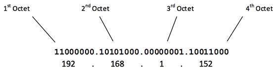
An IP address in IPv4 is 32-bits in size, which limits the address space to 4294967296 (232) IP addresses.IPv4 addresses are usually represented in dot-decimal notation, consisting of four decimal numbers, each ranging from 0 to 255, separated by dots, e.g., 172.16.254.1. Each part represents a group of 8 bits (octet) of the address.
The first octet referred here is the left most of all. The octets numbered as follows depicting dotted decimal notation of IP Address:
IP decimal notation
The number of networks and the number of hosts per class can be derived by this formula:
Number of networks
When calculating hosts' IP addresses, 2 IP addresses are decreased because they cannot be assigned to hosts, i.e. the first IP of a network is network number and the last IP is reserved for Broadcast IP.

Class A Address

                                                         The first bit of the first octet is always set to 0 (zero). Thus the first octet ranges from 1 – 127, i.e.Class A addresses only include IP starting from 1.x.x.x to 126.x.x.x only. The IP range 127.x.x.x is reserved for loopback IP addresses.The default subnet mask for Class A IP address is 255.0.0.0 which implies that Class A addressing can have 126 networks (27-2) and 16777214 hosts (224-2).Class A IP address format is N.H.H.H.

Class B Address

                                    An IP address which belongs to Class B IP Addresses range from 128.0.x.x to 191.255.x.x. The default subnet mask for Class B is 255.255.x.x. Class B has 16384 (214) Network addresses and 65534 (216-2) Host addresses. Class B IP address format is N.N.H.H.

Class C Address

                                    The first octet of Class C IP addresses range from 192.0.0.x to 223.255.255.x. The default subnet mask for Class C is 255.255.255.x. Class C gives 2097152 (221) Network addresses and 254 (28-2) Host addresses.Class C IP address format is: N.N.N.H.

Class D Address

                                     Very first four bits of the first octet in Class D has IP address rage from 224.0.0.0 to 239.255.255.255. Class D is reserved for Multicasting. In multicasting data is not destined for a particular host, that is why there is no need to extract host address from the IP address, and Class D does not have any subnet mask.

Class E Address

                                    This IP Class is reserved for experimental purposes only for R&D or Study. IP addresses in this class ranges from 240.0.0.0 to 255.255.255.254. Like Class D, this class too is not equipped with any subnet mask.

Internet Protocol Version 6 : In IPv6, the address size was increased from 32 bits in IPv4 to 128 bits or 16 octets, thus providing up to 2128 (approximately 3.403×1038) addresses. This is deemed sufficient for the foreseeable future.

Address Structure


                                                                                                                                                  An IPv6 address is made of 128 bits divided into eight 16-bits blocks. Each block is then converted into 4-digit Hexadecimal numbers separated by colon symbols.
For example, given below is a 128 bit IPv6 address represented in binary format and divided into eight 16-bits blocks:
0010000000000001 0000000000000000 0011001000111000 1101111111100001 0000000001100011 0000000000000000 0000000000000000 1111111011111011
Each block is then converted into Hexadecimal and separated by ‘:’ symbol:
2001:0000:3238:DFE1:0063:0000:0000:FEFB
Even after converting into Hexadecimal format, IPv6 address remains long.

Global Unicast Address

                                                                                                                                               This address type is equivalent to IPv4’s public address. Global Unicast addresses in IPv6 are globally identifiable and uniquely addressable.


[Image: Global Unicast Address]
Global Routing Prefix: The most significant 48-bits are designated as Global Routing Prefix which is assigned to specific autonomous system. The three most significant bits of Global Routing Prefix is always set to 001.

Link-Local Address

                                               Auto-configured IPv6 address is known as Link-Local address. This address always starts with FE80. The first 16 bits of link-local address is always set to 1111 1110 1000 0000 (FE80). The next 48-bits are set to 0, thus:


[Image: Link-Local Addres
Link-local addresses are used for communication among IPv6 hosts on a link (broadcast segment) only. These addresses are not routable, so a Router never forwards these addresses outside the link.

Unique-Local Address

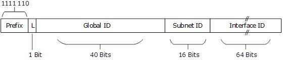
                                                                              This type of IPv6 address is globally unique, but it should be used in local communication. The second half of this address contain Interface ID and the first half is divided among Prefix, Local Bit, Global ID and Subnet ID.


[Image: Unique-Local Address]
Prefix is always set to 1111 110. L bit, is set to 1 if the address is locally assigned. So far, the meaning of L bit to 0 is not defined. Therefore, Unique Local IPv6 address always starts with ‘FD’.

Scope of IPv6 Unicast Addresses:


[Image: IPv6 Unicast Address Scope]
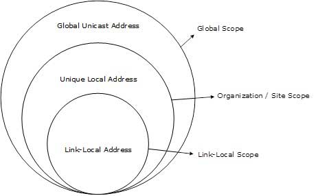
The scope of Link-local address is limited to the segment. Unique Local Address are locally global, but are not routed over the Internet, limiting their scope to an organization’s boundary. Global Unicast addresses are globally unique and recognizable. They shall make the essence of Internet v2 addressing.

Network

Thursday, 2 November 2017

OSI Model


The Open Systems Interconnection model (OSI model) is a conceptual model that characterizes and standardizes the communication functions of a telecommunication or computing system without regard to their underlying internal structure and technology. Its goal is the interoperability of diverse communication systems with standard protocols. The model partitions a communication system into abstraction layers. The original version of the model defined seven layers.


Layer 1 Physical Layer: It conveys the bit stream to electrical impulse, light or radio signal through the network at the electrical and mechanical level. It provides the hardware means of sending and receiving data on a carrier, including defining cables, cards and physical aspects. Fast Ethernet, RS232, and ATM are protocols with physical layer components.
Layer 2 Data Link Layer: At OSI Model, Layer 2, data packets are encoded and decoded into bits. It furnishes transmission protocol knowledge and management and handles errors in the physical layer, flow control and frame synchronization. The data link layer is divided into two sub layers: The Media Access Control (MAC) layer and the Logical Link Control (LLC) layer. The MAC sub layer controls how a computer on the network gains access to the data and permission to transmit it. The LLC layer controls frame synchronization and flow control. The FCS (Frequency Check Sequence) extra error-detecting code added to a frame in a communications protocol.
Layer 3 Network Layer: Layer 3 provides switching and routing technologies, creating logical paths, known as virtual circuits, for transmitting data from node to node. Routing and forwarding are functions of this layer, as well as addressing, internetworking, error handling, congestion control and packet sequencing.
Layer 4 Transport Layer: OSI Model, Layer 4, provides transparent transfer of data between end systems, or hosts, and is responsible for end-to-end error recovery and flow control. It ensures complete data transfer.
Layer 5 Session Layer: This layer establishes, manages and terminates connections between applications. The session layer sets up, coordinates, and terminates conversations, exchanges, and dialogues between the applications at each end. It deals with session and connection coordination.
Layer 6 Presentation Layer: This layer provides independence from differences in data representation (e.g., encryption) by translating from application to network format, and vice versa. The presentation layer works to transform data into the form that the application layer can accept. This layer formats and encrypts data to be sent across a network, providing freedom from compatibility problems. It is sometimes called the syntax layer.
Layer 7 Application Layer: OSI Model, Layer 7, supports application and end-user processes. Communication partners are identified, quality of service is identified, user authentication and privacy are considered, and any constraints on data syntax are identified. Everything at this layer is application-specific. This layer provides application services for file transfers, e-mail, and other network software services. Telnet and FTP are applications that exist entirely in the application level. Tiered application architectures are part of this layer.


Network

Wednesday, 6 September 2017

Internet Surface

Internet world is similar to our Universe like bright side and the dark side. In Internet system there is also two side one is surface web and another one is  deep web. Whatever i write in this page the reader can read this for knowledge only and I am not responsible for affecting or inciting anyone.
Surface Web : In this web which is visible and accessible for every one it is legal web. You can search any kind of web sites on google and google shows only visible and accessible web site which known as Surface Web. It has static and crawl-able web pages. In this web surface large amount unfiltered information. what is easily found by search engines is limited.
Deep Web : In this web which is invisible or hidden for security reason or password protected contents are stored in this web. It is also legal but some secret agency, banking and government authorized sectors can share their information through deep web that is why it is hidden. The deep web has long been blamed for the globalization of cyber-crime. In recent years, malicious and illegal commercial activities in dark net market are increasingly becoming common in many countries around the world. This has led to these platforms and their participants coming under increased pressure from authorities but that happened in Dark Web which is also the part of deep web. In dark web all illegal activity happened so it is very risky and harmful for others. If you want to access Deep Web you need to install Tor Browser. In surface web there sites like .com, .org etc. but In deep web sites like .onion.

Sunday, 3 September 2017

Transmission Media


Coaxial Cables : It is used by cable operators but sometimes ago it also used by telephone companies. Coaxial cable is a type of cable that has an inner conductor surrounded by an insulating layer, surrounded by a conductive shielding. Many also have an insulating outer jacket The diagram below illustrates the construction of a typical cable. Electrical signal flows through the center conductor.
Table. Common coaxial cable types and uses. There are many additional RG designations, as well as variations within each number class.
Cable type Ω Use
RG-6 75 Video, TV
RG-8 50 Radio, computer
RG-11 75 Long runs
RG-58 50 Radio, computer
RG-59 75 Video, TV


Advantages : 
1. Coaxial cable can support greater cable lengths between network devices than twisted pair cable.
2. Thick coaxial cable has an extra protective plastic cover that help keep moisture away and stronger.
Disadvantages :
1. Thick coaxial is not bend easily so, it is difficult to install.
2. Difficult to troubleshoot a simple issue.

Twisted Pair Cables : Twisted pair cable consists of a pair of insulated wires twisted together. It is a cable type used in telecommunication for very long time. Cable twisting helps to reduce noise pickup from outside sources and cross-talk on multi-pair cables.

The most commonly used form of twisted pair is unshielded twisted pair (UTP). It is just two insulated wires twisted together. any data communication cables and normal telephone cables are this type. Shielded twisted pair(STP) differs from UTP in that it has a foil jacket that helps prevent cross-talk and noise from outside source. In data communications there is a cable type called FTP (foil shielded pairs) which consists of four twisted pair inside one common shield (made of aluminum foil). The following are the cable types specified in ANSI/TIA/EIA which are mention below:


Category 1 : Cat 1 cable was originally designed for voice telephony only, but thanks to some new techniques, long-range Ethernet and DSL, operating at 10Mbps and even faster, can be deployed over Cat 1.

Category 2 : Cat 2 cable can accommodate up to 4Mbps and is associated with token-ring LANs.

Category 3 : Cat 3 cable operates over a bandwidth of 16MHz on UTP and supports up to 10Mbps over a range of 330 feet (100 m). Key LAN applications include 10Mbps Ethernet and 4Mbps token-ring LANs.

Category 4 : Cat 4 cable operates over a bandwidth of 20MHz on UTP and can carry up to 16Mbps over a range of 330 feet (100 m). The key LAN application is 16Mbps token ring.

Category 5 : Cat 5 cable operates over a bandwidth of 100MHz on UTP and can handle up to 100Mbps over a range of 330 feet (100m). Cat 5 cable is typically used for Ethernet networks running at 10Mbps or 100Mbps. Key LAN applications include 100BASE-TX, ATM, CDDI, and 1000BASE-T. It is no longer supported, having been replaced by Cat 5e.

Category 5e : Cat 5e (enhanced) operates over a bandwidth of 100MHz on UTP, with a range of 330 feet (100 m). The key LAN application is 1000BASE-T. The Cat 5e standard is largely the same as Category 5, except that it is made to somewhat more stringent standards. Category 5e is recommended for all new installations and was designed for transmission speeds of up to 1Gbps (Gigabit Ethernet). Although Cat 5e can support Gigabit Ethernet, it is not currently certified to do so.

Category 6 : Cat 6, specified under ANSI/TIA/EIA-568-B.2-1, operates over a bandwidth of up to 400MHz and supports up to 1Gbps over a range of 330 feet (100 m). It is a cable standard for Gigabit Ethernet and other network protocols that is backward compatible with the Cat 5/5e and Cat 3 cable standards. Cat 6 features more stringent specifications for crosstalk and system noise. Cat 6 is suitable for 10BASE-T/100BASE-TX and 1000BASE-T (Gigabit Ethernet) connections.
Category 7 : Cat 7 is specified in the frequency range of 1MHz to 600MHz. ISO/IEC11801:2002 Category 7/Class F is a cable is based on four twisted copper pairs, features even more stringent specifications for crosstalk and system noise than Cat 6. 
Advantages : 
1. Cheaper and far easier to splice
2. Less susceptible to electrical interference caused by nearby equipment or wires.
3. In turn are less likely to cause interference themselves.
4. Because it is electrically "cleaner", STP wire can carry data at a faster speed.
Disadvantages : 

1. STP wire is that it is physically larger and more expensive than twisted pair
wire.
2. STP is more difficult to connect to a terminating block.


Fiber Optics or Optical fiber Cable :  
A fiber optic cable is a network cable that contains strands of glass fibers inside an insulated casing. They're designed for long distance, very high performance data networking and telecommunications.
Compared to wired cables, fiber optic cables provide higher bandwidth and can transmit data over longer distances. Fiber optic cables support much of the world's internet, cable television and telephone systems.
Advantages :
1. One single mode fiber can replace a metal of time larger and heavier.
2. Multi-mode optical cable has a larger diameter and can be used to carry signal
over short distance.
Disadvantages :
1. Fiber optic versus metal cable is that it is difficult to make connections to
fiber optic cable.
2. The optical fiber must be highly polished to allow light to pass with little loss. 

Network

Saturday, 2 September 2017

Concept of Networking

Networking : The concept of networking is pretty simple. A couple of computers have some cables strung between them, and send data back and both using electrical signalling over the cable. More or less the same as telephones do or, in a very rough sense, like two kids speaking into tin cans connected by a string.
In simple way networking means two or more device can communicate with each other and sharing their respective information with the help of any kind of transmission media (wired or wireless).

Wired : In this scenario you can see that all device are connected with wired transmission media which known as Cable. In wired network, every desktop computer or device should be affixed to another desktop computers or a main appliance using cables.


Wireless : In this scenario all device connected with wireless media there is no using of any kind of cable. In other words wireless is the term used to describe any computer network where there is no physical wired connection between sender and receiver, but rather the network is connected by radio waves and/or microwaves to maintain communications.


 Types of Networks

LAN (Local Area Network) : It is a relatively small network covering small areas like a room, an office, a building, a campus etc. If you connect two computers for sharing data, you have a LAN. The number of computers connected on a LAN may be up to several hundreds, but most of the time, LANs are made up of more or less a dozen machines, as the idea behind a LAN is to cover a small area. The diameter of LANs can range from 100 meters to 1 kilometers.


MAN (Metropolitan Area Network) : It is a large computer network on the large geographical area that include several buildings or even the entire city (metropolis). The geographical area of the MAN is larger than LAN, but smaller than WAN. MAN includes many communicating devices and provides the Internet connectivity for the LANs in the metropolitan area.
MAN is used to combine into a network group located in different buildings into a single network. The diameter of such a network can range from 2 to 50 kilometers.

WAN (Wide Area Network) : It is a network that exists over a large-scale geographical area. A WAN connects different smaller networks, including local area networks (LANs) and metro area networks (MANs). This ensures that computers and users in one location can communicate with computers and users in other locations. WAN implementation can be done either with the help of the public transmission system or a private network. The diameter of WANs can range more than 50 kilometers
Network

Ad (728x90)


Copyright © Technical Agenda™ is a registered trademark.
Designed by Templateism | Distributed by Templatelib